

Radial Velocity Correction
The scalar radial velocity of the scatterers VR can be expressed as:
where VR meas is the Doppler velocity measured by the signal processor and VR ship is the radial velocity correction for ship motion. The radial velocity correction is found by taking the dot product of the antenna vector x in earth coordinates with the velocity of the antenna in earth coordinates yA, as follows:
The antenna vector is a unit vector pointing in the direction of the antenna which depends on the true (earth relative) azimuth and elevation of the antenna, as follows:
These are known from the antenna controller. Thus, the problem is to determine the yA, the velocity of the antenna.
The velocity correction used in IRIS allows for the following types of ship motion sensing:
- Inertial Navigation Unit (INU)
- (INU Case) The INU is typically placed close to the antenna. The INU reports pitch, roll, and heading (and their rates of change), as well as the east, north and vertical motion (u, v, w). In this case, the INU is used as the ship reference point.
- Gyro System with GPS
- (Gyro Case) The gyros report pitch, roll, and heading (and their rates of change). Mean translational motion of the center of the ship (u, v, w) is obtained from a GPS or other navigational system. In this case the ship center of rotation is used as the ship reference point.
The interface either device is the RCP antenna control unit. The orientation and navigation information is passed to IRIS through the serial line connection to the antenna controller.
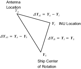
In general, the INU is not located at either the ship center of rotation or the antenna. The location vectors are shown in the previous figure in earth coordinates. The position vector of the antenna in earth coordinates can be expressed as:
INU Case:
Gyro Case:
so that,
INU Case:
Gyro Case:
where, and
Expressing the Δ vectors in terms of the ship relative coordinates yields:
INU Case:
Gyro Case:
Differentiating these two expressions yields the final expressions for the antenna velocity:
INU Case:
Gyro Case:
Note that since the INU, antenna and ship center coordinates are not changing relative to the ship coordinates,
The components of the matrix A-1 are as follows:
where:
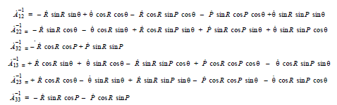
These equations show that the motion of the antenna can be expressed as a translational motion of a reference point (either at the INU or at the ship center of rotation), plus a rotational motion about a moment arm from the reference point to the antenna.
The translational motion of the reference point is:
As sensed by the INU for the INU Case:
As sensed by the GPS for the Gyro Case:
As a special case, if the INU and antenna are located at precisely the same position, then,
INU Case: so that
In this case, the antenna velocity is equal to the INU velocity since the moment arm is 0 length.