

Running Antenna in Sun Tracking Mode
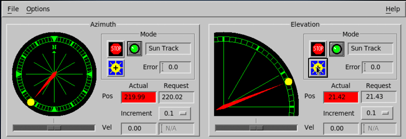
In sun tracking mode, the Antenna utility computes the direction to the sun from the radar location and positions the antenna there.
The purpose of the sun tracking mode is to test the alignment of the radar pedestal.
Because the sun is a black body radiator, it transmits microwaves that you can detect with your radar, even through the clouds.
The test consists of moving the antenna until you get the maximum return from the sun and then comparing the pedestal angles with the known position of the sun.
-
Stabilize and tune the antenna.
The antenna must accurately go to a requested position to within less than 0.2°.
-
Set your system time.
Vaisala recommends that you set the time to within a second of the correct time, though a 10 second error gives only a 0.05° error.
If you are using time synching, such as
ntp, set the time on the server system or turn synching off. -
Verify that your latitude and longitude are set correctly.
For a shipboard radar:
-
Perform the test when the sun is low in the sky.
At high elevations, the sun is so wide in azimuth that you cannot measure the azimuth offset accurately.
-
Configure and save a sun-track mode for Ascope.
We recommend turning off range normalization, displaying
Tonly, sample size of 256. -
In Antenna, start sun tracking mode by selection the sun icon.
In sun tracking mode, the position indicators are yellow circles displaying the sun's current azimuth and elevation positions.
-
Set the step to 0.2°.
-
Repeat the same test with the sun in a different azimuth direction (morning against
afternoon).
This allows you to differentiate a tip in the pedestal from a fixed offset.
-
Enter the measured errors in your antenna controller.
If you are unable to find the sun manually with small offsets, it may be because of a large unknown offset.
If the weather is clear, you may be able to spot the sun on the antenna to indicate the correct direction.
Alternatively, configure an IRIS sector scan centered on the sun and see if you can spot it on the real-time display. For RCP: