

Stable Platform Display
parameters are for shipboard or airborne applications where the antenna is stabilized by a radar control processor that is connected to an inertial navigation unit (INU).
The INU provides high-speed accurate information on the attitude (heading, roll and pitch) and position (East-West, North-South and height) of the ship.
The RCP uses this information to correct the antenna scanning for the ship motion, that is, the RCP moves the antenna in 'earth-relative coordinates' just as if the antenna were not on a moving platform. The concept of 'pedestal-relative coordinates' refers to how the antenna is moving relative to the pedestal, or since the pedestal is mounted on the ship, relative to the ship.
Since the motion of the ship effects the Doppler velocity, the Antenna utility also calculates the velocity correction that is required to remove the effect of ship motion.
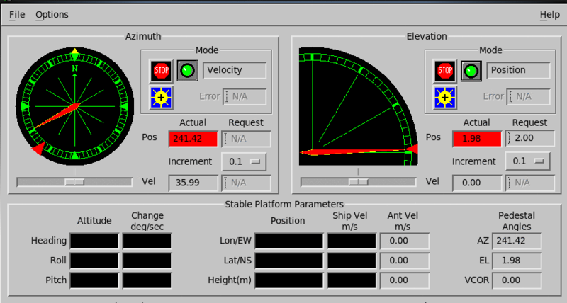
Attitude and Change
Train-order and elevation-order angles are displayed including the platform-relative pointing angles of the antenna pedestal.
-
Heading
The angle in which the bow of the ship points measured positive toward true North. Positive angles are clockwise.
-
Pitch
The up/down angle of the bow of the ship relative to the horizon. Positive angles are bow down.
-
Roll
The up/down angle of the side of the ship (normal to the long axis of the ship) relative to the horizon. Positive angles are port (left looking forward) side down.
Each of the above parameters are associated with rates of change in degrees/second.
Position and Velocity
The motion of the INU is described in the middle section of the display as shown below.
-
Long/EW and Lat/NS
Standard conventions are used for North/South and East/West.
-
Height (m)
The height of the INU rather than the antenna in meters above sea level.
-
Ship Vel m/s
The speed (vector (3D) velocity) of the INU, or the center of the ship in meters per second.
The first entry is positive east, the second entry is positive north and the third entry is positive up.
-
Ant Vel m/s
The 3D vector velocity of the antenna feed in meters per second. Generally different from the INU velocity.
The difference between the ship velocity and the antenna velocity is because the INU and the antenna feed are usually not co-located, that is, there is a moment arm between them. When the ship pitches, rolls and yaws, this moment arm induces a velocity.
 |
The INU is not assumed to be at the center of rotation of the ship. If you imagine yourself on a tall mast of a ship where antennas are typically mounted, the rocking of the ship is amplified by the mast. If the INU is located on the deck and the antenna is aloft, this difference is important. |
Pedestal Angles and Velocity Correction
Although the RCP corrects the antenna scanning for the motion of the ship, sometimes it is important to see the antenna position relative to the pedestal.
When the ship motion is severe, the antenna may be unable to achieve an earth relative elevation because the antenna encounters an elevation limit of the pedestal.
-
AZ
The azimuth angle of the antenna relative to the bow of the ship. Positive values are clockwise from the bow.
-
EL
The elevation angle of the antenna relative to the deck of the ship.
-
VCOR
The Doppler velocity correction required to compensate measured Doppler velocities for the ship motion.
The displayed velocity correction (Vcor) represents the velocity correction in meters per second that must be applied to the Doppler rate.
The Vcor computed by a dot product of the antenna velocity with a unit vector pointing in the direction of the antenna.