

Azimuth and Elevation Section
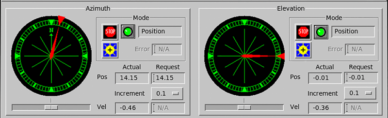
Azimuth Position Indicator
To set the azimuth position, move the arrow along the edge of the position indicator. The pointer displays the movement of the antenna to the new position.
Elevation Position Indicator
To set the elevation position, move the arrow along the edge of the position indicator. The pointer displays the movement of the antenna to the new position.
Mode
The Antenna utility can operate in the following modes:
-
Position
Enables setting the azimuth or elevation position.
-
Velocity
Enables setting the azimuth or elevation velocity.
-
Sun Tracking
Invokes a sun tracking procedure, which computes the direction to the sun from the radar location, and positions the antenna there. See Running Antenna in Sun Tracking Mode.
Stop
Select Stop to stop antenna movement, regardless of the current mode. The antenna slows to a stop as indicated by the pointer within the position indicator.
The stop light is red when the antenna is stopped and green when the antenna is running.
Sun Tracking
The blue and yellow Sun Tracking button puts the antenna into the Sun Tracking mode.
Select this button again to exit Sun Tracking mode.
Sun Tracking
While in Sun Tracking mode, before moving the antenna you can enter an offset to be added to the sun's position the Error field allows.
Sliding Scale
The sliding scales set the requested velocity for either the Azimuth or Elevation position. The scale has a "tick" at velocity 0. For the Azimuth velocity, positive speeds are for clockwise scanning while negative speeds are for counterclockwise scanning. For the Elevation velocity, positive speeds are for upwards scanning (toward the zenith), while negative speeds are for downward scanning (away from the zenith).
Position: Actual and Requested
The screen displays both the actual and requested position of the antenna, as they may differ.
When the antenna is in the Position mode, you may enter a position (in degrees) in the Request field. Both the Azimuth and Elevation positions can be observed to change and ultimately end up at or near the requested positions:
- Azimuth positions range from 0 ... 360º
- Elevation angles beneath the horizon are displayed as negative numbers.
 | The RCP has its own "soft" elevation limits. If the antenna elevation does not move all the way up or down, to fulfill a position request, the request may be outside the limits imposed by the RCP. Consult with your manufacturer if you are unsure. |
Some RCPs cannot move both axes of the antenna, in a velocity servo, at the same time. On these systems, the following message may be displayed at your request:
WARNING: Bad Combination of Servo Types.Velocity: Actual and Requested
The screen shows both the actual and requested velocities of the antenna, as they may differ.
When the antenna is in the Velocity mode, you may enter a velocity in the Request field. Enter the speed as a signed number (in degrees) per second. Six degrees per each second is equivalent to 1 RPM:
- For the Azimuth velocity, positive speeds are for clockwise scanning while negative speeds are for counterclockwise scanning.
- For the Elevation velocity, positive speeds are for upwards scanning (toward the zenith), while negative speeds are for downward scanning (away from the zenith).
If a velocity request exceeds the maximum velocity allowed by the configuration, set in the Setup utility, then the maximum velocity is substituted.
For example: If the upper limit in the Maximum Elevation field of the RCP section is 80° and you enter an elevation position of 90°, the Request field displays 80° and the antenna increases to that elevation. See Antenna Characteristics.
During installation, you must test this feature to verify that the protection is functioning properly. See Testing Antenna Safeguards.
Velocity and Increment
To set the Velocity field with the sliding scale, click inside the scale to move the slider.
To make fine adjustments, set the Increment field to 0.1 and click until the correct value appears in the Request field.
Platform Parameters
Use these parameters to manage the setting for moving platforms such as the pitch, the roll, and the heading angles and velocities.