

Status Panel
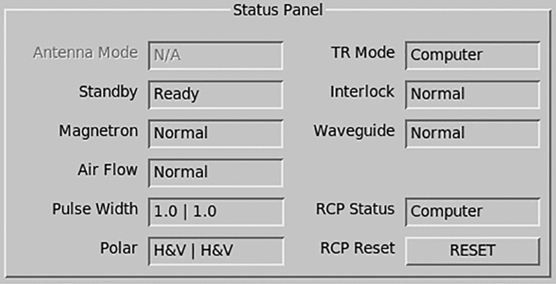
Ant Mode and TR Mode
The antenna and transmitter modes show the position of the control switch on the radar console and indicate when IRIS is collecting radar data:
-
Computer
The computer controls the antenna and RCP.
For normal operation, set the TR Mode to Computer and the Antenna mode to local mode.
-
Local
Antenna control requests from the computer are ignored, and the antenna is controlled manually using handwheels or a terminal connected to the RCP.
This mode is used for testing though, on some systems, you may record manual scans and run Ascope in local mode.
-
IRIS
Status when IRIS is controlling the antenna to record data. The control switch is set to Computer.
Other Status Indicators
Other status indicators report OK, Ready, or Fault. Not all systems have the same status indicators, but the following are typical on most systems:
- Air Flow refers to the flow of cooling air in the transmitter/receiver cabinets. This is usually sensed by a vane switch.
- Waveguide pressure is usually sensed by a pressure transducer.
- Interlock refers to the interlock on a door that protects a high-voltage or radiation hazard.
- Magnetron displays whether or not the magnetron current is within normal limits.
During installation, check the Antenna utility to verify that the sensors are properly installed and reporting to IRIS.
Pulse Width
- The first number is the pulse width that is currently being requested by the host computer.
- The second number is the pulse width status reported back from the RCP to the host computer.
The pulse widths here are referred to by index rather than microseconds. IRIS supports up to 4 pulse widths and the indices are labeled 0, 1, 2, 3. Most systems only use 2 pulse widths (0 and 1).
In most systems the RCP controls the pulse width. In this case you can use the control button next to the pulse width status field to change the pulse width. The selection menu displays both the index and the value in microseconds.
For systems where the signal processor controls the pulse width, this button cannot be used to change the pulse width. The proper request and status is reported however. Note that in this case the Ascope utility can be used to change the pulse width.
RCP Status
Indicates whether the RCP has shut down by displaying either OK or Shutdown.
RCP Reset
The RCP button resets the antenna controller. The button takes the antenna controller out of the shutdown state.