

Radar Site and Antenna Placement
To check or update radar placement information, select .
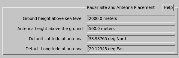
- Ground height above sea level
-
Enter the height above sea level (in meters) of the ground at the radar site. All product heights are referenced to this value.
If you wish to make products relative to sea level, enter 0 and put the ground height and tower height into the next question. If the radar is on a ship, then a value of 0 is appropriate.
- Antenna height above the ground
-
Enter the height of the radar antenna above the ground height chosen above. 1
- Default Latitude of antenna
-
Enter these values in decimal degrees with as many places of accuracy as desired (N and E are positive). 1
- Default Longitude of antenna
-
Enter these values in decimal degrees with as many places of accuracy as desired (N and E are positive). 1
Moving Platform Systems
- Antenna position ...
-
Enter the distance in meters from the inertial navigation unit (INU) location to the antenna location. This is recorded with the data and used for platform motion velocity corrections.
For example, if the INU is located in the middle of a ship at sea level, and the antenna is 10 meters (32 ft 10 in) above the sea, 15 meters (49 ft 3 in) to the stern and centered, enter the values -15, 0, and 10.
- INU height offset
- For moving platform systems that do not correctly measure the height of the INU, this number is added to what is reported by the antenna controller.
- Antenna Scan geometry
-
Choose from: Traditional and Aircraft Tail.
For an Aircraft Tail radar, the elevation angle scans continuously and the azimuth angle is the angle of the scanning cone, where 0 is perpendicular to the elevation axis.
See IRIS Product and Display Guide (M212928EN).
RCV03 format, this number (set in
meters) is overridden by the altitude reported from the antenna controller.