

Using the Digital Signal Simulator
You can use the signal simulator to simulate one or two targets that can occur both in the first trip or the first and the second trip to test the random phase range unfolding feature of RVP.
The simulator creates a time series across all range bins with the same statistics.
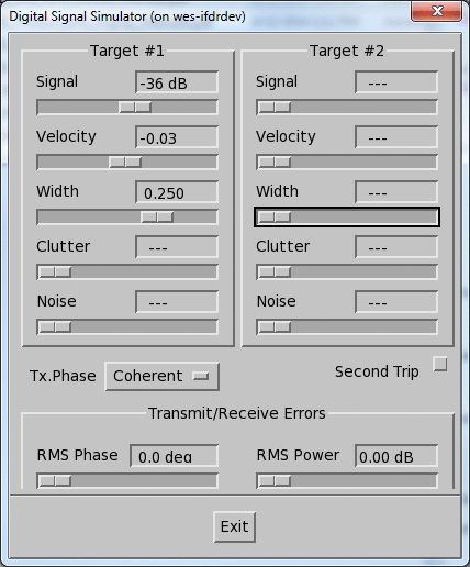
- Signal
-
Sets the signal power of the meteorological target (dB).
As you raise this value, the Doppler spectrum of weather increases in power.
If the Signal value is larger than the minimum slider value (---), the Signal, Velocity, and Width parameters define the Doppler Power Spectrum of a weather target with a Gaussian / Normal distribution.
- Velocity
-
Sets the mean radial velocity (m/s) of the weather target normalized between [-1, +1] to correspond to the Nyquist interval (fold point).
As you change this value, the Doppler spectrum moves horizontally.
- Width
-
Sets the spectrum width (standard deviation of velocity) in m/s.
As you change this value, the spectrum become broader.
- Clutter
-
Sets the power (dB) of the clutter signal which has a mean velocity of 0.
As you increase this value, the clutter peak at 0 velocity increases.
The power is calibrated in the same way as the signal power. For example, if both the Clutter and Signal powers are the same, the clutter-to-signal ratio is 0 dB.
- Noise
-
Sets the power (dB) of the white noise present. If
---then no noise added.Raising this value causes the noise floor to increase.
- Tx. Phase
-
Sets the sequence of phases used to modulate the time series from pulse to pulse:
Coherent - no phase modulation.
Random - random phase sequence.
For more information, see CFGPHZ host computer command in RVP10 User Guide (M212604EN).
- Second Trip
-
Adds a second trip to Target #2.
If Target #2 is in the second trip echo (Second Trip is enabled), the Tx. Phase parameters to give Target #2 a phase shift from Target #1.
- RMS Phase
-
Simulates phase noise. Increasing the phase noise increases the white noise level in the Doppler spectrum.
If the phase from pulse-to-pulse is the same, this setting defines amount of pulse-to-pulse Tx phase modulations of the simulated signal.
Typically, a magnetron radar has between 1 ... 3° of phase noise.
A Klystron system can have as little as 0.1° of phase noise.
- RMS Power
- Defines the pulse-to-pulse amplitude modulations of the simulated signal.
-
Select .
The simulator starts and the control panel is shown.
-
Configure Target #1.
Disable Target #2 by setting all of the Target #2 slide pots to the far left. This makes it easier to interpret your results.

Vaisala recommends that you display a Doppler spectrum with 128 samples so that you can see the results of any changes that you make.
When you are satisfied with the Doppler spectrum that you have constructed, you can switch to other types of displays.
-
Configure Target #2.
|
The signal, clutter, and noise signals for Target #1 and Target #2 are added together to form a single time series. |