

Treatment of Losses in Calibration
When calibrating the dBm level of the test signal, you must account for any losses that may occur between the antenna feed and the injection point, and in the cable and coupler that connect the signal generator to the injection point.
The following figure shows the nomenclature of the losses that are involved in the calibration.
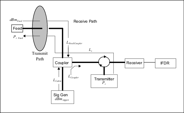
The relationship between the injected test signal and the value of the received power relative to the feed is:
For example, assume the following:
| Loss | Relationship | Value |
|---|---|---|
| Loss between the feed and the coupler | 3 dB | |
| Loss caused by the coupler | 30 dB | |
| Loss in the cable from siggen to coupler | 2 dB |
If the test signal generator output is -50 dBm, the injected power is
The equivalent power at the feed is then 3 dB more than this:
During the calibration, there are several ways to handle the losses using these equations. For example:
-
Correct each signal generator value for losses so that the calibration plot shows IFDR measured power against the received power at the feed.
This is recommended for manual calibration.
-
Plot the signal generator values directly and correct the intercept power
I0for losses so that it is properly referenced to power at the feed.This is the approach used by the IRIS Zauto utility. See IRIS and RDA Utilities Guide (M211316EN).