Dual System Architecture
The dual-system architecture features include:
- Two RCPs that coordinate the system operation via the A/B Comm Link. The RCPs monitor status from the radar, the signal processor, and IRIS, and decide between them which system is active.
- A “Disable Switch” that removes either system A or B. The switch (or 2 separate switches) could also be wired in such a way to make it possible to disable both A and B simultaneously.
- Two IRIS/Radar Systems that are treated as “unreliable” systems. In other words, even in the event of a failure of IRIS, RCP must still make the correct decision about which system is active.
- Two RVPs (radar signal processors) communicating with the IRIS Radar. Note that the 3 functions (RCP, RVP, and IRIS) are normally running on the same computer, but they can be implemented on 2 or 3 computers.
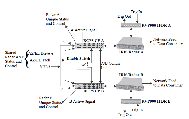
The following table summarizes the signals shown in the figure.
| Signal | Description | ||||
|---|---|---|---|---|---|
| Unique Status and Control | Status and control signals that are unique to each system. Examples are radiate on/off status and control, and transmitter status. These use the normal status/control and extended BITE inputs/outputs. | ||||
| Common Status and Control |
Status and control signals that are common to both systems. Examples of common status variables are waveguide pressure, safety interlock on the radome door, antenna servo status, and site/environment status. Common status inputs should be wired in parallel to both RCP8s to the normal status and BITE inputs.
Examples of common control outputs are servo power on/off and any environment control such as obstruction light on/off. Common control functions must be handled differently to prevent the possibility of simultaneous, and perhaps conflicting, control by both RCP. Critical control functions (that is, those that could potentially damage the radar if both RCPs were to command them), should be routed through an external relay that is controlled by the A/B Active Indicator signal (which can of course be used to control a master relay). Non-critical control functions (that is, those that would not damage the radar if both RCPs were to command them), can be routed through any of the spare internal relays in RCP8 (there are 8 total). The approach of using spare internal relays for these common control outputs relies on the RCP8 control logic equations. The internal variable cDrcpActive would be equated to one of the extended BITE control output variables. This would be physically wired to a spare TTL relay on RCP8. The control output would then be wired through the relay (for example, servo power on/off). This approach is not fail‑safe, since the user could make an error in the control logics, or simply disable the control logics. Therefore it is not appropriate for critical control functions. |
||||
| Azimuth and Elevation Drive Output Signals |
Routed through an internal relay in RCP8 that connects the drive lines when RCP8 is in the active state. This allows only 1 RCP to control the antenna. The normal drive output back panel connector assignments are used. |
||||
| Azimuth and Elevation Tachometer Input Signals | Wired in parallel to the tachometer inputs on both RCPs. Tach is sensed by both RCP8s simultaneously, but is not used on the inactive unit. The normal tachometer input back panel connector assignments are used. | ||||
| Trigger Inhibit | Output line from RCP to the signal processor or trigger
generator that can be used to inhibit triggers on the inactive system.
In the case of an RVP, the line is the LSB of the normal azimuth output
tag line (AZ0). No special cabling is required. |
||||
| A/B Active Indicator Output Line |
This is an active low TTL signal that is output to indicate that an RCP8 is in active mode. This signal should be used directly to switch (via external relay) critical control functions, that is, those functions that, if operated simultaneously by both RCP8s could cause damage to the system. The internal logic
variable name for this indicator is |
||||
| A/B Disable Switch Input |
A switch closure to ground on this input disables a system so that it is not available for automatic switching. This is used, for example, to put a system in “Maintenance Mode”. The input can be implemented as a single, three position selector
switch as shown in the figure, or as two separate switches. In the
case of a single selector switch, the switch can be labeled as an
enable rather than a disable (for example,
|
||||
| A/B Communications Link |
This link is on a special cable between 2 RCP8s. The link implements a serial protocol that passes status information and requests for control between the 2 RCPs. For information on pin assignments, see Dual System Cabling and Modifications. |