
Dual System Cabling and Modifications
Dual System Connection Cable and Switch
All cabling requirements for the dual-system are handled on connector J3, a 25DBF connector on the back panel of RCP8 labelled CONTROL. This connector contains the input for the A/B Disable Switch, the output for the A/B Active Indicator signal and the A/B Communications link. The wiring is shown below. For signal information, see Dual System Architecture.

- 1
- cDrcpComm[0]
- 2
- cDrcpComm[1]
- 3
- cDrcpActive (A or B is ActiveSignal)
- 18
- sDrcpComm[0]
- 19
- sDrcpComm[1]
- 20
- sDrcpEnable
- 24
- GND
- 25
- GND
Antenna Drive/Internal Relay Wiring
The cabling to route the output drive signals through the internal relays is shown in the following figure.
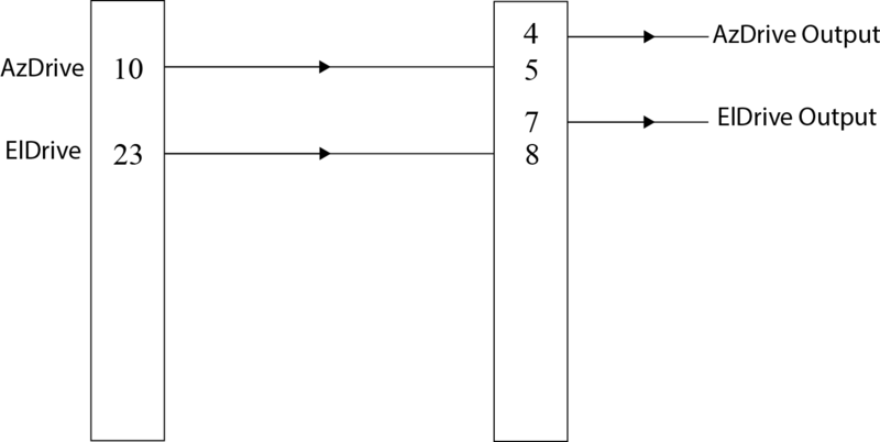
You must modify the softplane.conf file to control the internal relays as follows:
- splConfig.Io62[0].Opt.Cp.J6_IntRelay2 = "cDrcpActive"
- splConfig.Io62[0].Opt.Cp.J6_IntRelay3 = "cDrcpActive"