
IRIS Dual System Switching Menu
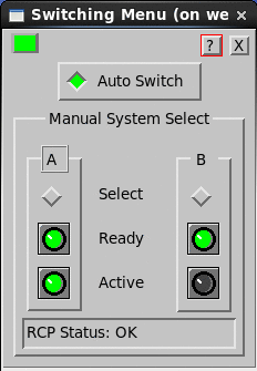
The dual system Switching Menu provides a interface for controlling and monitoring the dual‑system by allowing the operator to:
- See which system (A and/or B) is ready for operation, and which one is currently active (only one is active at any time).
- Select the exclusive use of either A or B, or enable automatic switching, which occurs in the event of a fault.
By default, the menu is set for automatic switching. The menu can run locally at either Radar A or B, or remotely over the network to allow remote controlling and monitoring.
When running the menu on system A, the menu communicates directly to RCP8 A through RCP–to–IRIS serial line and indirectly to B through RCP–to–RCP communications link.
 |
The Switching Menu does not control RCP8 switching, rather it submits switch requests to RCP8s, which then negotiate whether the request can be fulfilled. For example, if the operator requests that System A be used, but system A is not available because it is in fault or has been disabled by the hardware A/B switch, then the request is not fulfilled. In this case neither system becomes active. If the operator requests auto switching (the recommended mode of operation), then RCP8s negotiates to activate the available system. |
The following table shows the contents of the Switching Menu.
| Button or Light | Possible Values | Description |
|---|---|---|
| Flashing Light (upper left) |
|
The flashing light at the top-left indicates that the menu is live. |
| Auto Switch |
Green -OK |
For normal operation Auto Switch is enabled. This allows RCP8s to negotiate which system to use. However, operators can request the use of only system A or B. For normal maintenance functions however, you should select a single system should be done using the hardware A/B selector switch at the radar and keep the Switching menu in the Auto position. Sometimes it is useful to temporarily force the systems to switch and then immediately reset back into the Auto mode, just to exercise or test the other system. |
| Ready |
|
Shows the system status and whether the hardware A/B switch at the radar is set to disable the radar. For a system to be used for operation, Ready must be green (status OK) and the Bezel must be gray (not disabled). This makes it easy to see whether the system is ready for operation, and if not, what course of action would make it operational. |
| Active |
|
An active indicator is also displayed on the RCP8 front panel. See RCP TTY Site Settings for Dual System. The RCP8 front panel either On or --. |
| Status field |
|
If there is a failure, shows red and describe the nature of the failure. If there is a failure, X symbols appear over the status indicators for the system for which communication has failed. See Troubleshooting Dual Systems. |