

Configuring receiver gain
The configuration of the receiver gain involves a trade-off between receiver sensitivity and dynamic range. As the gain gets higher, the sensitivity gets better, but the dynamic range gets lower. The higher gain improves the noise figure and, thus, the sensitivity of the receiver. However, the A/D converter also begins to saturate at weaker signal levels at the receiver input. This trade-off is illustrated in figure Trade-off between dynamic range and sensitivity.
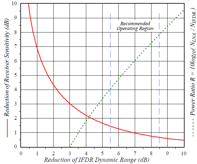
NIFDR represents the stand-alone (terminated input) noise power of the IFDR over some bandwidth.
NLNA represents the Rx path (LNA/Mixer) thermal noise power over that same bandwidth at the input of the IFDR.
Calculation example:
Select (1 dB reduction IN sensitivity, and 7 dB reduction in IFDR dynamic range).
The desired noise level of the Rx parts at the IFDR input is as follows:
If the noise figure NF(dB) of the Rx parts is 2 dB, then the desired Rx gain is as follows:
, where -174 dBm/Hz is the noise level of a matched termination at room temperature, and 1 MHz is the noise bandwidth of the signal.
The dynamic range estimate is
When designing your RF and IF components, remember that the final amplifier driving the IFDR10 must be capable of driving sometimes up to +17 dBm, for example, so that signals above saturation can be correctly measured.
After assembling all the RF and IF components, check whether you have the correct gain by verifying a 7 dB rise (independent of bandwidth) in RVP10 filtered power, when the IF- Input cable is connected and disconnected. (NIFDR = -84 dBm, NLNA = -78 dBm, (NLNA+NIFDR) = -77 dBm, resulting in the 7 dB difference).