

Filters
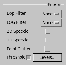
Doppler Filter, LOG Filter
These fields show the current filter selection.
You can select the clutter filter by number. RVP has filters numbered 0 ... 7.
 |
Filter 0 is equivalent to no clutter filter. |
See RVP10 User Guide (M212604EN).
2D Speckle Filter and 1D Speckle Filter
The speckle remover thresholds a data bin for which the bin before and after are already thresholded.
Use this toggle button to clean random data from the display.
Point Clutter
Turns on/off the point clutter remover.
This is a NEXRAD algorithm which runs on the I/Q stream before the data moments are computed. If it sees a sudden spike in power, it replaces the average values from before and after in range.
Thresholds
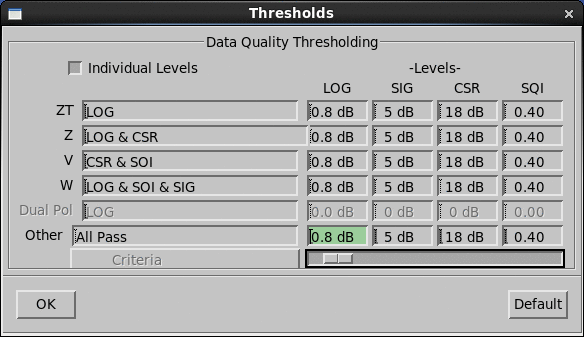
The signal processor uses thresholding to removes range bins that have weak signal power or unreliable estimates of the Doppler parameters.
-
Select Thresholds to turn thresholding on and off.
-
Select Levels to set threshold criteria and levels.
See Antenna Overview and RVP10 User Guide (M212604EN).
Criteria for thresholding are set for each data parameters (ZT, Z, V, W, Dual Pol, and Other). You can choose to discard the data when one or more of the following threshold parameters are weak:
-
LOG
LOG receiver signal-to-noise ratio.
-
SQI
Doppler channel signal quality index.
-
CSR
Doppler channel clutter-to-signal ratio.
-
SIG
A measure of the power from weather targets, excluding noise.
You can select, or enter any Boolean
equation using the variables SQI, LOG,
CSR, and SIG, separated by and
and or.
Choose or enter All Pass to accept any value, in effect turning off thresholding.
To select thresholding levels, enter a value directly or move the sliding scale until the value you want appears in the field.
- LOG
-
Sets the LOG receiver threshold in dB above noise.
If thresholding is turned on and the LOG video signal is below this threshold level, reflectivity is thresholded on the reflectivity plots.
Enter a value of 0 ... 5 dB.
- SIG
-
Sets signal power threshold level in dB above noise.
Often this is used to threshold widths.
If the LOG video signal power is below this threshold after removal of clutter power, the widths are thresholded.
Enter a value of 0 ... 20 dB.
- CSR
-
Sets the clutter-to-signal ratio threshold.
If the ratio exceeds this threshold, and thresholds are enabled, the Doppler data are thresholded.
Enter a value of 0 ... 50 dB.
- SQI
-
Sets the Doppler threshold level.
Similar to the LOG threshold level except that it is for the Doppler channel signal quality index.
If the processor computes an SQI less than the threshold defined here, the velocity and width data for that range bin are not plotted.
You can enter a value of 0 ... 1.
A value of 0 causes nearly all data to be plotted; 1 causes nearly nothing to be plotted. A value of 0.3 generally eliminates the weak signals and passes signals that have good mean velocities.
The "noise points" that get by the threshold correspond to speckles on the color display.
This is useful for reducing the amount of data that is transferred to serial line graphics displays.
After you have entered your thresholding criteria and levels, select OK to apply your settings and exit the menu.
To reset the values to their defaults, select Default.