

Adjusting burst pulse timing
You must calibrate the burst pulse timing separately for each pulse width. Each iteration is independent.
-
Set up the relative timing for all used RVP10 triggers.
The trigger output lines are interchangeable, and each may be assigned to any function within the radar system.
For example,
Trigger #1might be the transmitter pretrigger,Triggers #3and#4might synchronize external displays, andTriggers #2,#5, and#6might be unused. -
Choose an initial impulse response length of 1.5 times the transmit pulse width.
This length is refined later when the passband filter is designed.
See Burst spectra and AFC plot (Ps).
If using the matched filter, adjust the pulse length so that just the rising and falling edges of the burst are captured.
-
Adjust the plot time span to view a small region around the sample window, and set the
initial amplitude zoom to x16.
This assures that the plotted waveform is still noticeable, even if the burst signal strength is very weak.
-
Verify that the transmitter is radiating, and observe the burst pulse samples on the
display.
Use the L and R commands to shift the timing of all 6 triggers relative to range zero. This moves the burst sampling window relative to the transmitted pulse.
Depending on whether the triggers are set properly, you may at first see nothing more than a flat line of misplaced A/D samples. However, after a few moments of hunting, the burst pulse should appear on the display screen.
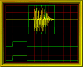
- Fine-tune the triggers so that the burst envelope is centered in the window, and adjust the amplitude zoom for a comfortable size display.
-
Isolate the clean center portion of the burst pulse isolated to a narrower sub-window
of the overall FIR interval.
Use the A and S commands to change the aperture and start of the narrowed region from which the AFC frequency estimators data are derived.
Figure 1. Burst timing plot for a properly captured burst pulse using a matched filter (on the left) and a passband filter (on the right). 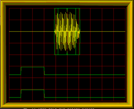
-
Check that the burst pulse signal strength is reasonably matched to the input span of
the IFDR A/D converter.
The maximum analog signal level is +12 dBm. Exceeding this level produces distorted samples that would seriously degrade the algorithms for phase locking and AFC. However, if the signal is too weak, then the upper bits of the A/D converter are wasted and noise is unnecessarily introduced.
Vaisala recommends a peak signal level between -3 dBm and +4 dBm, that is, a signal that might be viewed at x2 or x4 zoom.
Take note of the burst energy level reported on the TTY. It helps decide the minimum energy threshold for a valid burst pulse.