

Burst pulse analysis for amplitude, frequency, and phase
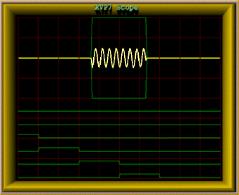
The burst pulse analysis provides the amplitude, frequency, and phase of the transmitted pulse.
Amplitude measurement can provide enhanced performance by allowing the I and Q values to be corrected for variations in both the average and the pulse-to-pulse transmitted power. A warning is issued if the burst pulse amplitude falls below a threshold value.
-
The burst pulse data stream is first analyzed by an adaptive algorithm to locate the burst pulse power envelope (for example, 0.8 μsec).
The algorithm does a coarse search for the burst pulse in the time/frequency domain (by scanning the AFC). It then does a fine search, in both time and frequency, to assure that the burst is centered at range 0 and is at the required IF value.
- The power-weighted phase of the burst pulse and the total burst pulse power is computed.
- The power-weighted average phase is used to make the digital phase correction.
Phase jitter for magnetron systems, with good quality modulator and STALO, is better than 0.5° RMS, as measured on nearby clutter targets.
The burst pulse frequency is also analyzed to calculate the frequency error from the nominal IF frequency. For magnetron systems, the error is filtered with a selectable time constant, which is typically set to several minutes to compensate for slow drift of the magnetron. The digital frequency error is sent through the uplink to the IFDR in the receiver cabinet.