
Data quality thresholding
The signal processor performs thresholding to ensure clean displays, promote efficient execution and transmission of the products, and reduce the amount of tape and disk space required to hold compressed data and product archives.
| Concept | Description |
|---|---|
| Threshold | IRIS edits data in real time to remove range bins with weak signal power, unreliable estimates of Doppler parameters, or polarimetric parameters that suggest echo is of undesired origin, for example not precipitation. |
| Parameters | Each threshold parameter has its own user-defined threshold level. See the following table. |
| Threshold Criteria |
The parameter to use as the criterion. For example, the Z values could be discarded when the log receiver signal is weak. Likewise, V values could also be discarded when the log receiver signal is weak. In both cases, LOG is the threshold criterion for thresholding Z and V. |
| Threshold Levels |
Acceptable levels for the signal. Using the same example, the threshold level for the LOG may be set at 1 dB above noise. In this case, the velocity and reflectivity are discarded if the LOG receiver power does not meet or exceed 1 dB above noise. This is done on a bin-by-bin basis. For each range bin, the values of the threshold parameters are computed and compared with the user-defined threshold levels. The result is either a "pass" or "fail" for each threshold parameter. |
| Parameter | Threshold level |
|---|---|
| LOG Level (dB)1 |
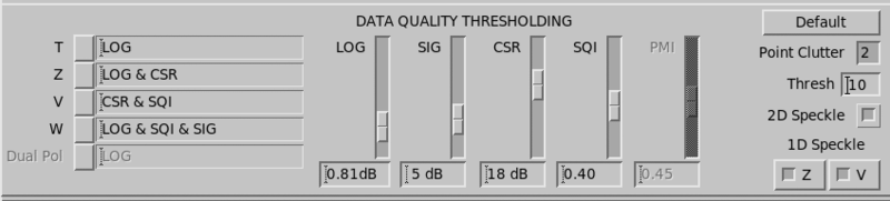
The receiver signal-to-noise ratio. The average LOG channel power (dB) at each range bin is compared to the LOG threshold level (typically 1 dB). A LOG level of 0 dB represents the noise floor. If the measured LOG power at a bin is greater than the threshold, the range bin is "passed" for LOG. |
| SQI Threshold [0,1]1 |
Doppler channel signal quality index (SQI). A measure of the coherence or Doppler power of the linear channel. The SQI is 0 ... 1, where 0 corresponds to a signal that is "white noise" (no coherent power) and 1 corresponds to a signal that is a perfect point Doppler target (all power is coherent). An SQI greater than approximately 0.4 is required to measure mean velocity and spectrum width. If the measured SQI at a bin is greater than the threshold, then the range bin is "passed" for SQI. |
| CSR Threshold (dB)1 |
Doppler channel clutter-to-signal (CSR) ratio. The CSR compares the ground clutter power to the meteorological signal power in the Doppler channel. The CSR is calculated for each range bin and compared to the user-defined threshold, typically set to 20 ... 40 dB depending on the coherence of the transmitter/receiver system. If the measured CSR at a range bin is less than the threshold level, then the bin is "passed" for CSR. |
| SIG Level 1 |
A measure of the power from weather targets, excluding noise. Refers to the weather signal power. That is, the signal-to-noise ratio corrected for clutter. This is typically set to about 10 dB, and used to threshold widths. This is because the spectrum width cannot be measured from a very weak signal. If the measured SIG at a range bin is greater than the threshold level, then the bin is "passed" for SIG. |
| PMI Threshold1 |
Polarimetric meteo index (PMI), available at polarimetric radars operating in the mode of H+V transmission. Describes the consistency of the
data with the hypothesis of precipitation (the default preference). The estimate is
obtained from the ratio of the rule strengths of the As default, the ratio is transformed
into a score function that lies smoothly between 0 and 1, where 0 corresponds to a
signal that is unlikely The value 0.45 is the threshold
where the pre-classifier declares the bin |
Threshold levels and criteria
The threshold criterion controls whether a particular type of data (T, Z, V W, and Dual Pol) should be accepted for each range bin by defining which thresholds to apply to each of these output parameters.
For example, the reflectivity is usually set so that the Z values (and T) is accepted if the LOG test passes. As a further constraint, you can accept the corrected reflectivity values (Z) only if both the LOG and CSR tests pass. This assures not only that the signal is strong enough for a good estimate, but that the ground clutter is not so strong that the estimate is unreliable.
To set the threshold levels, position the cursor on the appropriate level field and type the value or move the slider within the scale until the desired value is displayed in the field.
To change the threshold criteria, enter a value in the field or select an option for each parameter from a list of choices.
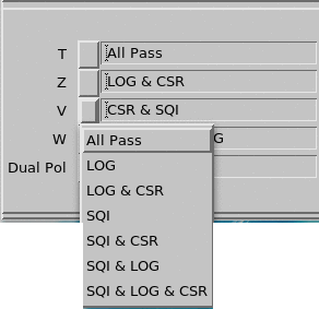
 | All Pass means that any value is accepted, and thresholding values are ignored. Polarimetric variables are treated identically to Dual Pol. |
Defaults
Select Defaults to reset thresholding to the default values.
Point Clutter Filter
Point Clutter is a target that has strong total power in one or two successive range bins but is bordered on either side in by bins of significantly lower power. Meteorological targets rarely appear this way, but aircraft and ships do.
The Point Clutter Filter is effective in removing small, strong targets having some velocity causing standard clutter suppression to not work as well.
The Point Clutter Filter is applied in the signal processor using the autocorrelation data (T0, R0, R1, and R2) after the Doppler spectrum clutter filtering. A range bin is flagged as containing clutter if its total power (T0) exceeds that of its neighboring range bins by more than a specified detection threshold (in dB). The neighboring range bins may be configured to be up to 3 bins away from the central bin. This is used with small bin resolutions, such as 25 meters, as some point targets appears in more than one successive range bin. When a range bin is flagged, the averages of the autocorrelation values from its neighbors are assigned to the flagged range bin. In this way point clutter can effectively be removed from data, even when contained in valid meteorological data.
Select PntCtl to toggle on or off the Point Clutter suppression feature of the signal processor. The number in the toggle selects how far away the neighboring range bin should be along the radial for the comparison.
The Thresh field defines the detection threshold (0 ... 20 dB).
Speckle Filters
A speckle is a range bin that has valid data but is bordered on either side in range by bins with invalid data (empty bins). Meteorological targets rarely appear this way, but towers, aircraft and "lucky noise" do.
IRIS provides buttons for enabling or disabling the 2 D Speckle and 1 D Speckle speckle filters.
IRIS includes separate 1 D Speckle filters:
- Z - LOG channel parameters (for Z, T and ZDR)
- V - Linear channel parameters (for V and W)
Vaisala recommends toggling off the speckle filters initially and adjusting the number of samples so that there are only a few speckles on the real time display. After the adjustments, you can toggle on the speckle filters for a cleaner display.
 |
If increasing the number of samples would make the task too slow, you can also adjust the LOG or SQI threshold level for Z/V until only few speckles remain. |