

SLINE: Shear Line
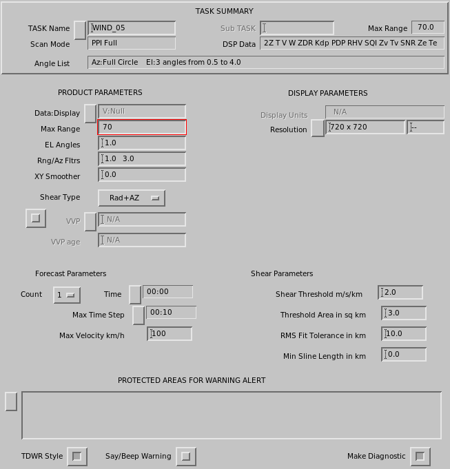
SLINE marks the transition between two air masses on the image.
Because the wind can be different on either side of the air mass, sudden wind shifts occur when a frontal boundary passes.
The following figure shows an example of a typical shear line. The most severe wind shifts are associated with mesoscale gust fronts, which occur at the leading edge of a thunderstorm outflow, and with larger scale cold fronts, which may be associated with severe weather.
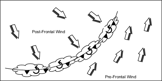
The SLINE product can detect sudden wind shifts and provide advance warning of their approach, with best estimates of the arrival time and the expected speed and direction of the new wind.
- Select .
- To load an existing product, select
-
In Data:Display, select
V Shear. -
In EL Angle, define the elevation angle of
data you want to display.
Wind shears associated with gust fronts and microbursts are usually low-level phenomena, so angles of 1° or less are typically used to detect these.
You may select 1 or 2 angles. If you select 2 angles, make sure both are above the threshold to be included in the shear line.
-
Define Rng / Az Filter.
The first number defines the range length scale for the SHEAR product, in km. This distance determines the size of the skip that the SHEAR product can tolerate when differencing over missing data. It also specifies the length of the radial smoother, which is applied before the XY smoother.
The second number is the azimuth length scale in degrees.
The skipping and azimuth range length are analogous to the range filter.
-
In Shear Type, select which type of shear you want to
compute:
-
Radial Shear
The bin-to-bin difference in the radial velocity.
-
Azimuthal Shear
The azimuth-to-azimuth difference in the radial velocity.
-
Elevation Shear
The difference between the radial velocity at the selected and next higher elevation angle. Requires a volume scan.
-
Combined Shears
The RMS value of the radial, azimuth, and/or elevation shear. This is sometimes referred to as the total shear.
-
-
In VVP, select the name of a VVP product.
The wind speed and direction from the nearest VVP wind product of this name is used to remove the effects of the mean wind on the azimuth shear calculation.
This VVP product must be scheduled to run. Use of the azimuth or combined shear is not recommended without this correction.
-
In VVP Age, specify the maximum number of minutes between the
data for the VVP product and the data for this product.
This prevents old VVP winds from being misapplied. If a VVP product is not found in this time window, the mean wind correction is not applied when computing the azimuth shear.
-
Define SLINE settings:
- Count and Time
-
Enter the number of forecast points and the time interval between each forecast point and select Ok.
The time you specify is inserted in the field.
- Max Time Step
-
The forecast of shear line motion uses the previous shear line product.
Max Time Step specifies how far back in time the previous SLINE product can be. If none exists in this time frame, no forecast is made.
- Max Velocity
- Enter the maximum expected velocity. If the computed velocity exceeds this value, the shear line is considered to be a new feature, and no forecast is made.
- Shear Threshold
- Enter the minimum speed difference per km that must be present to indicate a shear line. Winds that do not meet this speed are ignored.
- Threshold Area
- Enter the minimum size of the wind shear area in square km that must be present to indicate a shear line. Wind shear areas below this threshold are ignored.
- RMS Fit Tolerance
- Enter the standard deviation allowed when fitting the shear line. The line is discarded if the points do not fit within this tolerance, indicating a random scattering of points and not a shear line.
- Minimum Sline Length
- Enter the minimum length distance in km used to estimate a shear line. Shear lines that are below this length are ignored.
-
Configure SLINE for use with warnings.
- Protected Areas for Warning Alert
-
Specify one or more protected areas. A warning is generated if a shear line is within a protected area or is forecast to move into one.
Select Protected Areas to see a list of areas and toggle a choice on or off. When you exit the list, the names of the selected areas are displayed in the field.
Protected areas are configured with the Setup utility. They are constrained to be rectangles with arbitrary size and orientation angle. Up to 32 areas can be configured.
If you make a change to Setup, you must restart IRIS for the change to take effect. See IRIS and RDA Utilities Guide (M212925EN).
- TDWR Style
-
IRIS supports two formats of warning messages.
In TDWR format, only the strongest centroid in the highest priority area is reported along with its strength. For example:
MBA 3MF 30K–, in spoken language: Microburst Alert, Three Mile Final, 30 Knot loss.The older IRIS format reports all centroids in all protected areas, for example:
3 MBA warnings at 11:30 in: 3MF, 2MF.The messages are displayed at the bottom of the display screen, and optionally spoken.
- Say Warning
-
When enabled, the product generator to audibly signals the warning message in addition to displaying it as a message.
You must also select in IRIS.
-
To troubleshoot or test SLINE products, enable a thresholded
version of the input SLINE product by selecting Make
Diagnostic Results.
This has the same product name as the SLINE.