

Optimizing SHEAR for Microburst Detection
Accurate detection and timely reporting of microbursts in an air traffic control environment requires that the system be properly configured and optimized.
Vaisala recommends you work with a qualified consultant to assist with tuning and evaluating the IRIS SHEAR algorithm, data acquisition, radar siting and warning reports.
 | The optimization steps presented here are only guidelines and should not be substituted for a thorough evaluation of your particular site. IRIS provides many of the tools needed to perform such an evaluation. |
The radial velocity can be expressed in terms of the
u and v components of the wind (the vertical
velocity is ignored here because the observations are typically near
horizontal: |
|---|
|
where: Vr is the radial velocity
θ is the azimuth defined as positive CCW from the x-axis (East) φ is the elevation defined as positive upward Let the wind be represented by a
mean wind The azimuth derivative is then, where the first term is the apparent azimuth shear caused by the mean wind. Thus, when the azimuth derivative is computed, the correction term is applied as follows: The values of
|
The SHEAR product is first produced from tasks that are optimized for close-range, high-resolution measurement of radial velocity.
The SHEAR products are then fed to the WARN product, which checks to see if the strength and size of the wind shear regions exceed a threshold value in the protected areas.
Additional criteria, such as reflectivity aloft from a higher scan or a requirement to see the shear on two adjacent scans, can be added to the WARN product to reduce the false alarm rate if this is a problem for the particular location.
-
Setup an IRIS configuration for wind shear, so that when potentially hazardous weather
approaches the terminal area, IRIS can be switched to wind shear monitoring mode by
loading the configuration into the Radar Status menu.
You can a operate the WARN product in surveillance mode to alert the operator that the mode should be switched, or the automatic mode switching feature can be used.
For example, the surveillance mode could consist of a 15 elevation volume scan sequence. The WARN product can be keyed on a severe storm indicator such as VIL. If VIL exceeds a threshold value typical of severe storms for the area, and this VIL is within 30 km (18.6 mi) of the terminal, the WARN product can issue an alarm advising the operator or the automatic mode switch to change to the wind shear detection mode.
-
Optimize the TASK Configuration menu for wind shear detection as
shown in the example in the following figure.
This example uses high-resolution sampling in range (125 or 62.5 m (205 ft 1 in)). Microbursts are low-level phenomena, so it is best to configure elevation angles that are as low as can be tolerated by the surrounding clutter.
Typically an angle set such as 0.5°, 1.0° and 5.0° is useful. The bottom 2 angles can be used for shear detection, while the upper angle can serve as the basis for an additional reflectivity aloft criterion for the WARN product. Sector scan mode is used to limit the data coverage to the terminal area which speeds the update rate.
Figure 1. TASK Configuration for Microburst Detection 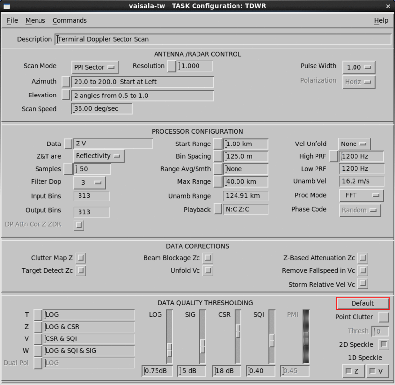
-
Set the TASK Scheduler in wind shear detection mode to provide
an update rate (repeat time) of at least one complete task per minute.
To provide optimal response, do not schedule other tasks. This allows IRIS to devote its full resources to detecting microbursts.
-
Optimize the SHEAR product configuration:
-
Set the Product Range field to the maximum range of interest, and should roughly correspond to the input bin spacing.
The 30 km (18.6 mi) range and 480 by 480 pixel product resolution in the example match the 125 m (410 ft 1 in) sampling in the task.
In the example elevation angles of 0.5, 1.0, and 5.0, separate shear products can be configured for each of the lowest 2 angles.
-
It is recommended not to use any additional XY smoothing when the SHEAR product is used for microburst detection because smoothing tends to diminish the peak values that are of interest in the shear calculation.
The radial smoothing performed by the range filter, and the subsequent smoothing performed in the WARN product are adequate.
The WARN product looks at the SHEAR products to determine whether to issue a warning. In the example of 2 low-level scans (0.5º and 0.9º), each with its own SHEAR product, the WARN product can be set to examine each. A threshold level of 8 m/s/km is a good indicator of hazardous wind shear. A 1 km (0.6 mi) area threshold can be used which corresponds to roughly 64 pixels for the case of 125 m (410 ft 1 in) bin spacing, 30 km (18.6 mi) range and 480 × 480 product resolution.
-
-
Optimize the Product Output menu to send the
WARN product to a workstation so that personnel can view the
situation display.
- Make the automatic output request so that the shear product is sent every time that it is made.
- Make sure a workstation is running the IRIS menus so that when windshear is detected, the audible warning message and text can be viewed.
Warning messages are issued almost instantaneously when wind shear is detected. Within a few seconds of receiving a warning message, the situation display is presented. This depends on the speed of the communications link connecting your display. However, because the situation display is an overlay product without a complex picture, it can be transmitted efficiently.
-
Tune the wind shear detection algorithms for each site.
This requires that qualified personnel perform the necessary optimization for your particular meteorological and operational environment.
You must go through a thorough evaluation phase to test your system on your particular site for your particular weather.
It is recommended that you make and record a RAW product every time a microburst is detected and perform an analysis to determine if it was a real event or a false alarm.
To obtain a larger sample, you may want to expand the protected area to include all the total area around the radar to the maximum range of detection required (typically 20 to 30 km (12.4 to 18.6 mi)) for air terminal applications. A qualified meteorologist should assist with this evaluation.
-
If it is determined that false alarms are occurring, there are several approaches you
can take to balance sensitivity against false alarm rate.
In tuning your system to reduce false alarms, it is important to make gradual changes and evaluate them on test cases that you have recorded. Some examples of actions that you can take to reduce false alarms are as follows (note the reverse of each example can be used to increase sensitivity):
- Gradually increase the range filter in the SHEAR Product Configuration menu from 1 to 2 km (0.6 to 1.2 mi).
- Increase the SHEAR magnitude threshold in the WARN Product Configuration menu.
- Increase the threshold AREA size in the WARN Product Configuration menu up to 2 km (1.2 mi).
- Require that 2 low-level scans from the same task both detect the SHEAR in the WARN product: a two-look test.
-
Add a warning criterion that requires reflectivity aloft. This can be based on a dBZ PPI at a higher angle.
Make sure dry microbursts are not common in your area. If they are, you may need to use a VIL criterion and employ more elevation angles in your associated task.