

Digital IF bandpass design tool
The digital matched filter computes I and Q interactively using a TTY and oscilloscope for graphical display.
You can choose the filter's passband width and impulse response length, and RVP10 constructs the filter coefficients. You can display the frequency response of the filter and compare it to the frequency content of the transmitted pulse.
Microwave energy can come from a variety of transmitters such as ground-based, ship-based, or airborne radars as well as communications links. To minimize the risk of substantial interference to a weather radar system, RVP10 supports interference rejection algorithms. See Interference filter.
IFDR10 places the WDR I and Q samples on the Ethernet line, where they are sent to the computer's processor. The I and Q values are then processed to extract the moment information (Z, V, W, and optional polarization parameters).
Using the digital IF bandpass filter
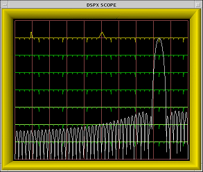
You can use the filter design tool to design the optimal IF filter to match each pulse width and application.
To show the filter, specify the impulse response and pass band. Use keyboard commands to widen or narrow the filter and to automatically search for an optimal filter.
This display can also show the spectrum of the transmit burst pulse for quality control and comparison with the filter.
For more information on the tool, see chapter Plot-assisted setups.