Configuring NDOP Products

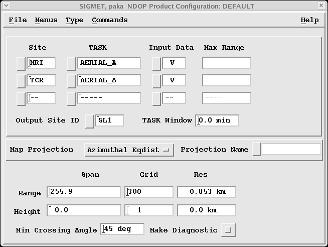
Figure 1. NDOP Example Configuration
  1. In the top section of the NDOP configuration window, specify the tasks and sites.
    1. To select a site, select the Site button.
    2. To select a task based on the ingest files on your system, select the TASK button.

      If the task you want is not in the list, type the task name. You can use IRIS wildcard conventions, such as:

      • PPI*

        Use any task that starts with PPI.

      • PPIVOL_A

        Use only the A part of the hybrid task.

      • PPIVOL_BC

        Use only the BC parts of the hybrid task.

      If you have specified a single task, the range field is filled-in with the maximum range of the data for that task.

      If you use a wildcard or hybrid task specification the Range field is blank.

    3. Select the input data, V or Vc (radial velocity or corrected radial velocity).
    4. To enter a site ID associated with the product output, select Output Site ID.

      When the NDOP products appear in inventories such as the Product Output Menu or Quick Look Window, they are associated with this site.

    5. In the TASK (time) Window, specify is the maximum time difference that is tolerated for combining the data from the two radars.

      If the difference in the task start times is greater than this value, NDOP does not make the product. This prevents problems caused by advection and temporal changes that could cause inappropriate winds to be combined. A value of 2 minutes is typical.

  2. In the middle section of the NDOP configuration window, specify the map projection for the product.

    The projection should be at a convenient point perhaps between the radars and cover a range that is no more than approximately 4 times the baseline length. This is typically the useful range of the NDOP product.

    If you do not specify a Projection Name, the data is centered on the location of the first radar site in the list.

  3. In the bottom section of the NDOP configuration window, specify the output resolution by specifying the characteristics of the grid.

    The NDOP product produces wind vectors on a 3D grid.

    1. Specify the Range Span.

      The Range Span is the distance in km from the center of the projection, east to the edge of the projection, analogous to a radar range.

      It is specified in the named projection. If you are not using a Projection Name, type the range.

      A max range of about 4 times the baseline length is typical.

    2. Specify the Range Grid.

      The Range Grid is an integer that specifies the number of points in the output array representing the Range Span.

    3. For the Height Span, specify a maximum and minimum height (km).
    4. Specify the Height Grid.

      The resolution is then calculated from:

      Height Res = (Max Height - Min Height) / (Height Grid - 1)

    The Resolution (Res) is a display-only field calculated from:

    Range Res = (Range Span) / (Range Grid)

    In the example, the Range Span is 40 and the grid is 16, therefore the resolution is 2.5 km (1.6 mi). The actual number of points in the output array that is made by NDOP depends on the aspect ratio of the projection, which may not be square.

    For a square projection and a grid specification of 16, the output array would be 32 × 32.

  4. In the bottom section of the NDOP configuration window, specify Min Crossing Angle.

    This is the minimum crossing angle that is used. The recommended value is 20°. The same value is used by the algorithm to specify the maximum crossing angle, that is, the max crossing angle = 180 - Min Crossing Angle.

  5. If needed, enable Make Diagnostic.

    When enabled, the NDOP product makes additional velocity CAPPI products, with product names NDOP_CAPPI_#. These are the input data used by NDOP.