

Configuring Status QBITE Points
In QBITE, a quantitative value is passed. It is a packet in the an integer number of bytes in the data packet, using 7 bits/byte.
-
Start Bitex with the
-setupoption. - Right-click the data point.
-
In the QBITE Status Field Configuration Menu, update
the configuration.
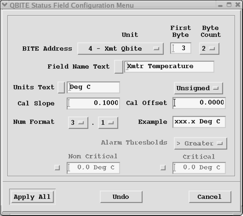
- BITE Address
-
The BITE address specifies which byte and bit in the BITE packets from the RCP corresponds to this status item. The BITE address has 3 parts:
-
Unit
Corresponds to the one of the
Received Status Bitsunits defined in the Bite Customization Menu. -
Byte
For this unit, what byte is used for this data point. Limited to a range between 3 and a customized number of bytes (
N) minus 1 for this Unit (bytes 1, 2, andNare reserved). -
Bit
Corresponds to the bit (in the Unit and Byte numbers) that this data point is mapped to. Limited to the range 0... 6.
-
- Field Text Name
-
The text string that appears on this data point that defines its meaning (up to 19 characters).
- Units Text
- A short string to display next to the QBITE value.
- Cal Slope, Offset, and Signedness
-
The QBITE value is computed by first concatenating all the bytes together from the data packet. We then interpret this number as either a signed or unsigned integer, which is then multiplied by a slope, and an offset is added. Specify this here.
- Num Format
- Specify how many digits to show when displaying the QBITE value.
- Alarm Thresholds
-
Controls fault generation. You can configure the system to generate both a critical and a non-critical fault based on the QBITE value.
Specify the threshold values and whether it should alarm above or below the threshold.