

Configuring Control Data Points
-
Start Bitex with the
-setupoption. - Right-click the data point.
-
In the Control Field Configuration Menu, update the
configuration.
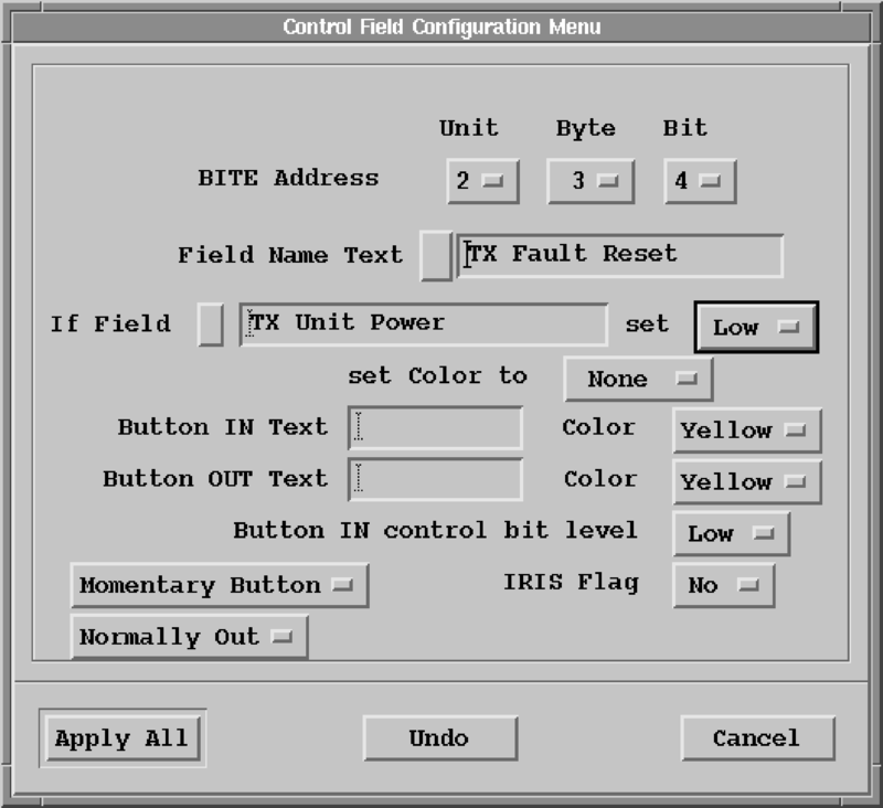
- BITE Address
-
The BITE address specifies which byte and bit in the BITE packets from the RCP corresponds to this status item. The BITE address has 3 parts:
-
Unit
Corresponds to the one of the
Received Status Bitsunits defined in the Bite Customization Menu. -
Byte
For this unit, what byte is used for this data point. Limited to a range between 3 and a customized number of bytes (
N) minus 1 for this Unit (bytes 1, 2, andNare reserved). -
Bit
Corresponds to the bit (in the Unit and Byte numbers) that this data point is mapped to. Limited to the range 0... 6.
-
- Field Text Name
-
The text string that appears on this data point that defines its meaning (up to 19 characters).
- If Field
-
Allows for the button color to change based on some condition.
Select the button to the right of If Field and choose the conditional data point, low, high, or None.
To disable this feature, select None.
To change the color that the button changes, select the button next to set color to.
- Button IN / OUT Text and Color
- Allow text information to be displayed next to the button depending on of the button is pressed in or out.
- Button IN control bit level
- Sets the polarity of the data bit corresponding to this button.
- Momentary Button / Toggle Button
- Configure buttons to be momentary (you must be applying pressure for the button to stay in) or as toggle buttons.
- Normally Out / Normally In
- Selects the normal position of the button.
- IRIS Flag
- When set to Yes, a message is sent to IRIS when the state of the button changes. The message is put into the message log and status product.
- Select Apply All.