

Configuring Status Data Points
-
Start Bitex with the
-setupoption. - Right-click the data point.
-
In the Status Field Configuration Menu, update the
configuration.
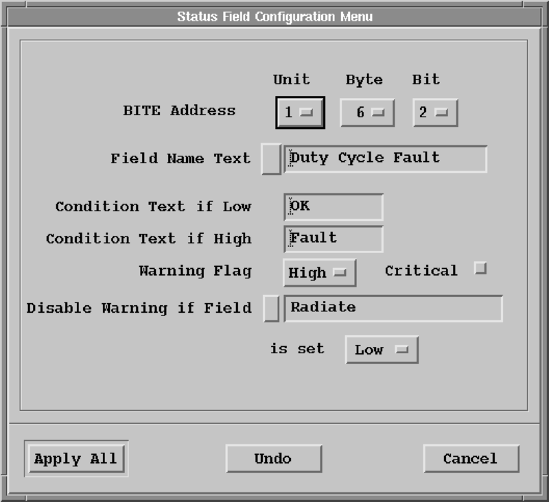
- BITE Address
-
The BITE address specifies which byte and bit in the BITE packets from the RCP corresponds to this status item. The BITE address has 3 parts:
-
Unit
Corresponds to the one of the
Received Status Bitsunits defined in the Bite Customization Menu. -
Byte
For this unit, what byte is used for this data point. Limited to a range between 3 and a customized number of bytes (
N) minus 1 for this Unit (bytes 1, 2, andNare reserved). -
Bit
Corresponds to the bit (in the Unit and Byte numbers) that this data point is mapped to. Limited to the range 0... 6.
-
- Field Text Name
-
The text string that appears on this data point that defines its meaning (up to 19 characters).
Select the button on the left of the field to choose a pre-defined text string. If a pre-defined field name is used, the allows Antenna utility recognizes this data point as a "special meaning" data point, and the Antenna utility displays the setting of this data point. This is only applicable to systems that require an INU (moving platform radars).
- Condition Text if Low / High
-
Allow the display of optional text depending on the reported state of this data point.
If entered, this text is displayed on the left side of the actual data point display.
This text can be up to 9 characters long.
- Warning Flag
-
Controls fault generation. This can be set to None, Low, or High.
None means not to generate a fault based on this bit, otherwise the warning flag indicates the level considered a fault. If a fault is possible, the fault can be further conditioned with the Disable Warning field.
If the warning flag is set (value other than None), then if the data point is in the unfaulted state, the LED indicator is green. If the data point is in the faulted state, the data point is displayed as either yellow (non-critical), or red (critical) depending on the state of the Critical button (next to the Warning Flag selection).
If the warning flag is set to a value other than None, then this data point is or'ed into the overall status of this site. Thus this data point could cause this site to be considered faulted, or critically faulted. This information can be used by the RCP to allow channel changing in system employing redundancy.
- Disable Warning
-
Lets you override a warning if a particular field is set to Low or High.
Use this when a condition should generate a warning only some of the time.
For example, a
High Voltage Missingcondition does not require a warning if the transmitter is turned off. By specifying this additional BITE condition, you disable the warning.
- Select Apply All.