

Pulse Width Definitions
The parameter window is different according to whether the Polarization Diversity parameter in Optional Data Parameters is set to Enabled or Disabled.
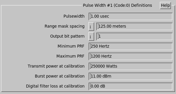
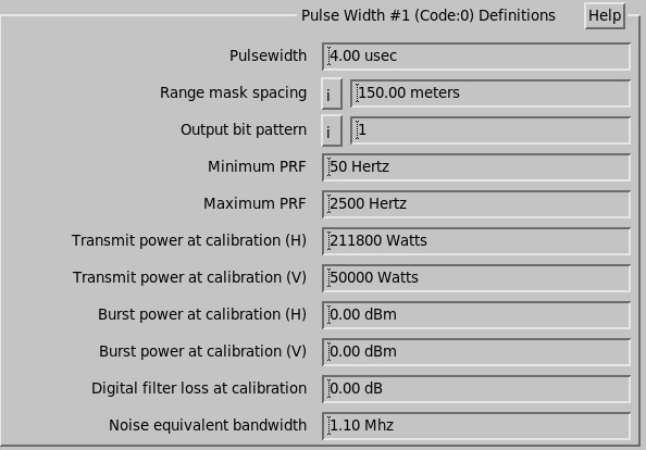
Each pulse width has its own set of configuration parameter values:
- Pulsewidth
-
Enter the first pulse width (usually the shortest) in microseconds.
Setup prompts for the other pulse widths.
- Range Mask Spacing
-
Set this value to match to the spacing (in meters) between successive bins in the range mask of your signal processor.
The value varies depending on the type of signal processor, and with the choice of acquisition clock frequency.
The resulting bin spacing (that should be copied into this setup slot) is printed in the RVP TTY dialog.
- Output bit pattern
-
Enter the base 10 value of the 4-bit output signals that the signal processor uses to control pulse width.
Recommended values are 1, 2, 4, and 8 for pulses #1 ... 4.
This has no effect on systems that do not use the signal processor to control the pulse width.
- Minimum PRF
- Check with your manufacturer to see if there is a lower limit. A value of 160 Hz is usually acceptable.
- Maximum PRF
-
Enter the maximum PRF in Hz allowed for pulse width #1 (specified above).
Setup prompts for all pulse widths.
Use the PRF limit corresponding to the longest pulse width (this should be the lowest maximum PRF). This guards against cabling errors.
- Transmit power at calibration
- Enter the peak transmit power (Watts) for each pulse width. Set unused pulse widths to 0.
- Burst power at calibration (H)
- Burst power at calibration (V):
- Digital filter loss at calibration