RVP calibration
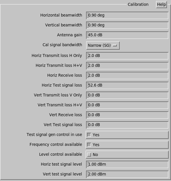
The following parameters are shown when Polarization Diversity is enabled:
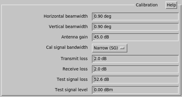
The following parameters are shown when Polarization Diversity is disabled:
- Horizontal beamwidth/Vertical beamwidth
- Type the horizontal and vertical antenna half-power beam widths in degrees.
- Antenna gain
- Type the antenna gain on the axis of the antenna in dB.
- Cal signal bandwidth
-
- For a normal signal generator enter Narrow.
- For a noise source enter Broad. For noise sources, enter the ENR value.
For noise source, you must use a single point calibration, for a signal generator you must use multiple power levels.
- Horiz/Ver Transmit loss
- Type the transmitter power loss values in dB between the transmitter and the antenna feed.
- Horiz/Ver Receiver loss
- Type the receiver loss values in dB from the feed to the receiver. This is usually the same as the transmitter loss.
- Horiz/Vert Test signal loss
- In performing calibrations, a test signal generator is injected into the system. This accounts for any loss of test signal power in the connection between the test signal injection point and the receiver. Losses in the cabling and in the directional coupler are usually included here. These losses may also be calibrated out when you set up your signal generator.
- Internal test signal gen. in use
- Select whether internal test signal generator is in use.
Answering Yes activates the test singal level fields.
If Polarization Diversity is disabled in the optional data parameters, then only one field is available.
- Horiz test signal level
- Type the horiz test signal level.
- Vert test signal level
- Type the vertical test signal level.
 |
For dual polarization radars, you can type loss values for the horizontal and vertical channel to deal with differences in the waveguide, as well as correcting for transmitter power effects. |
 |
Single polarization and simpler configurations have fewer loss values. |
Example
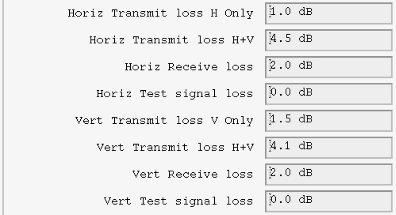
In the following example, we assume that the horizontal and vertical powers are both 200 kW, with a 1.0 dB loss in the horizontal waveguide, and a larger 1.5 dB loss in the vertical waveguide.
We also assume that in H+V mode, the power splits unevenly with 90 kW to horizontal and 110 kW to vertical. This gives 3.5 and 2.6 dB losses over the full power case. This is added to the waveguide losses to get 4.5 and 4.1 dB.