

Scanning Options
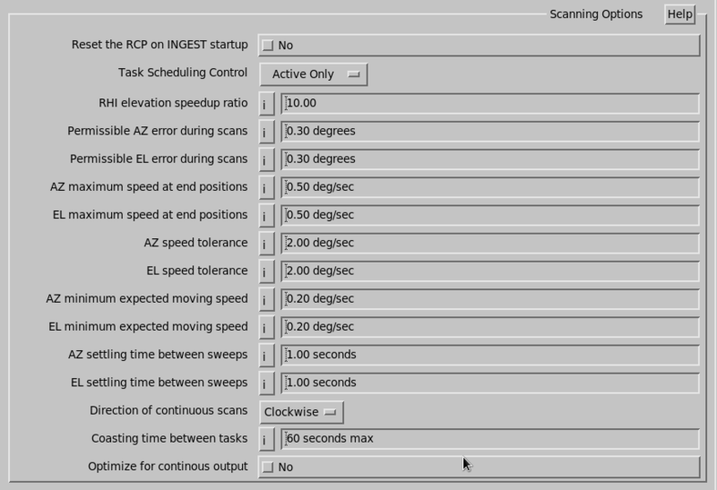
- Reset the RCP on Ingest Startup
-
Causes an Error Reset command to be sent to the RCP when the
INGESTprocess starts. The reasons that you might want to do this are:- In dual/redundant systems, the reset clears any error conditions that may accumulate while the RCP was inactive. These generally are not real faults, and it is safe to clear them automatically.
- In single radar systems the reset helps to insure that the RCP is ready to respond to ingest's commands.
- With the reset enabled, you can then
clear RCP shutdown conditions easily from the IRIS Radar
Status menu by toggling the
INGESTprocess Off/On.
The main reason not to select the automatic reset is that you may prefer a policy in which RCP shutdowns are always manually handled by an operator, after first determining that the original cause of the failure has been repaired.
- Task Scheduling Control
-
Normally set this to Active Only.
IRIS supports a Passive mode of data collection in which it is slave to other radar control software. In this mode, IRIS monitors the azimuth, elevation, and PRF of the radar and attempts to match it with the tasks in the task schedule, and to record data. See IRIS Radar User Guide (M212926EN).
If Passive Only or Active/Passive is selected then the Passive Type is specified.
- Passive Type
-
The choices are:
-
Multi-Tasking
Used for PPI Full scanning when the system controlling the antenna does one or more volume scans. In this case there can be more than one task in the task schedule.
-
Single Tasking
Used for any scan mode (Sector, RHI, PPI Full, Manual). In this case there may only be one task in the task schedule.
-
Status Slaving
Can be used for any scan mode (Sector, RHI, PPI Full, Manual) and there can be multiple tasks in the schedule.
The controlling computer must send a
STATUSproduct to IRIS to signal which task is about to start. In this case, there is an additional question to provide the Slaved to Site Code (three letter site code of the site sending theSTATUSproducts. -
TS Playback
This can be used for any scan mode (Sector, RHI, PPI Full, Manual) and there can be multiple tasks in the schedule. Use with
tsarchiveto play back recorded data.The task is selected based on the name recorded with the data.
-
- RHI elevation speedup ratio
- During RHI scans, the antenna velocity is increased at higher elevations in order to save time. This parameter controls how much faster the antenna goes at 90° elevation compared to 0°. This is typically set to 10.
- Permissible AZ/EL error during scans
- The IRIS system insists that the antenna get to within this angular distance of any desired position before proceeding. The tolerances are in degrees, and are typically set to about 0.5°.
- AZ/EL maximum speed at end positions
-
These speed limits work in together with the above position limits.
When the antenna is positioned within the angle tolerance, it must also be moving at a speed less that these maximums. This prevents falsely proceeding in the case of an underdamped antenna which moves quickly through its settling position several times before coming to a stop. The speed limits also help to remove the initial elevation "starting trail" during continuous PPI scans.
Vaisala recommends the setting of 0.5°/s.
- AZ speed tolerance
- At the start of each sweep, IRIS waits until the antenna speed is within the value of the requested speed. This prevents the sweep from starting while the antenna may be still moving too fast.
- EL speed tolerance
- Same as above for RHI Full sweeps.
- AZ/EL Min expected moving speed
-
When IRIS is positioning the antenna using the above angle and speed criteria, it is possible that success is never attained. This can happen if the antenna gets stuck before reaching the destination, or if it oscillates endlessly around that point.
During any repositioning operation, IRIS first calculates a maximum time to wait based on the angular distance to be traveled and the minimum moving speed given here. Five seconds are added to compensate for edge effects.
IRIS proceeds after this time limit expires, regardless of what the antenna is doing. This prevents endless waits resulting from antenna defects.
Typical values are 1.0 to 5.0°/s. A value of 0 result in a fixed 5-second maximum wait.
- AZ/EL min settling time between sweeps
- These minimum times allow IRIS to work better when the step between tilts is very small. In addition to the above criteria for determining that the antenna is close to a desired position, IRIS waits these minimum times.
- Direction of continuous scans
-
You can specify whether continuous PPI scans go clockwise or counterclockwise.
To equalize the wear on the gears, Vaisala recommends that you change this every few months.
- Coasting time between tasks
-
If the number of seconds between 2 continuous scan PPI tasks is less than this number, IRIS does not stop the antenna between the tasks. This can prevent wear on the antenna.
Set this value to 0 to always stop between tasks.
- Optimize for continuous output
-
If set to Yes, the following changes are made compared to the legacy behavior:
- Leave the DSP in continuous output mode between tasks.
- If the same task is running
continuously, skip reading the
gparmdata at the start of the task. This means it would not detect faults like burst pulse missing. - Do not set the sweep number value between sweeps.
Set the value to No unless you want continuous real-time displays.
For continuous displays, disable the noise sample in ingest.
When set to Yes, you should see only about 1 ray missing between tasks at 3 rpm 1° resolution. Consider using instead the real-time data sent directly from RVP.