

Checking Receiver Bandwidth
Test Goal
Verify the receiver bandwidth is in excess of 14 MHz.
Background
For proper functioning of the high speed A/D convertors, RVP requires approximately 14 MHz of broadband noise.
This noise does not interfere with the signal to noise ratio because the bandwidth filter is applied afterwards. The bandwidth of the anti-aliasing filter should be the limiting factor.
This test uses the same hookup as Checking Calibration and Dynamic Range.
For dual polarization systems, you can expect a narrower bandwidth.
Test Equipment
KVM connected
RF signal generator
Test Procedure
- Connect the test signal generator to inject a signal at RF ahead of the LNA.
-
Enter the TTY setups through
dspx. - Enter the Pr mode and make the following settings:
- Use the space bar to toggle to the power spectrum plot.
- Use the L/l and R/r commands to set the start to 50 μsec.
- Use the T/t command to set the plot span to 50 μsec.
- Use the V/v command to set averaging to 1 sample.
- Set the signal generator power to a value that is approximately 60 dB above noise and observe the scope plot.
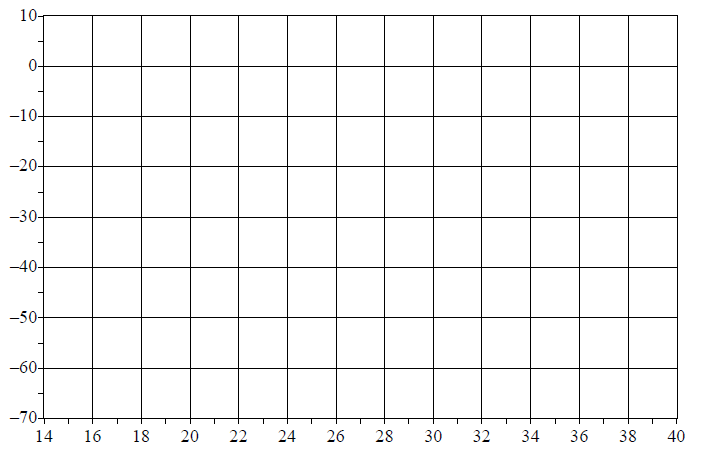
- Adjust the frequency of the test signal generator in 1 MHz increments to cover the whole range of the scope plot. Mark the total power measured on the plot in the following graph.
- Verify that the 3 dB point gives approximately 14 MHz of bandwidth.
Checklist
| Task | Checked OK/Not OK | Remarks |
|---|---|---|
| Test procedure completed successfully. | ||
|
Parameters are set. |
||
| Test Passed | ||
| For Customer | Date: | |
| For Vaisala | Date: | |