

WIND: Wind Speed and Direction
WIND displays wind speed and direction with either wind bards or wind strings.
WIND computes a 2-D array of horizontal wind vectors (the horizontal wind field) using the radial velocity information and the assumption that the wind is uniform over a limited sector (for example, 10 km (6.2 mi) by 60°). By computing the mean wind in a number of sectors, an approximation to the 2-D field of horizontal winds can be made. Because the algorithm assumes uniform winds over a sector, it is also called the "sector uniform wind algorithm." The algorithm can show gradual changes in the wind vectors over the radar coverage area. It cannot show sharp gradients such as fronts or microbursts.
The output can be displayed as wind barbs or wind strings as an overlay product. The mean wind can be subtracted at output so that the perturbation wind is displayed. These selections are made when the product is displayed in the Quick Look Window or the Product Output Menu using the Output Options.
 |
If there are insufficient radial wind points in a sector, the algorithm still computes a mean wind. However, the estimate is unreliable. For each sector, the total number of valid velocity range bins found is stored, as well as the total number expected for full coverage. When displaying the results, the output options allow thresholding by the percentage of coverage in a sector. Use this threshold to reduce noisy values. A value of 40 % areal coverage is a good starting point. |
- Select .
-
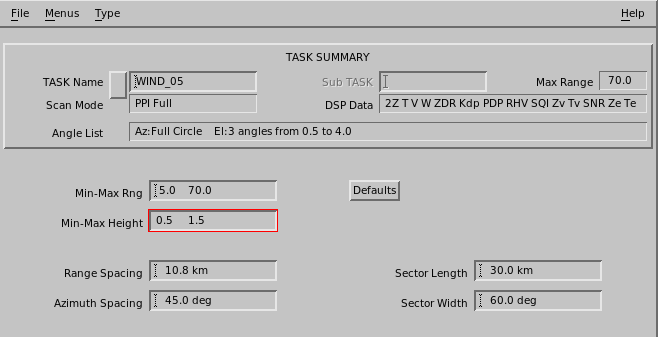
In Min-Max Rng specify the radius of the product, starting at a
point close to the radar and ending at some distance away from the radar.
Wind vectors are computed only within this range.
-
In Min-Max Height define the layer from which the radial
velocity information is taken to produce the wind vectors.
Because vertical shear can be substantial, Vaisala recommends that this layer be ~1 km (~0.6 mi).
-
In Range and Azimuth Spacing, define the
resolution for computing the wind vectors in polar coordinates.
For example, if the Range Spacing is set to 10 km (6.2 mi) and the Azimuth Spacing is set to 45°, a wind vector is computed over the Min-Max Range every 45° in azimuth and 10 km (6.2 mi) in range.
-
Set the Sector Length and Width
values.
Each wind vector is computed at the center of a sector which is defined by the Sector Length (or range) in km and the sector width (or azimuth) in degrees.
You can set the Range and Azimuth Spacing so the sectors overlap.
Vaisala recommends that the sector width be ~60°.
- In Defaults, set all fields in this menu to their default values.